
Amateur radio is the only hobby that offers its licensed operators the chance to legally design, build and operate high-power radio transmitters connected to unlimited antenna arrays for communication anywhere in the world. The most complex part of this communication system is the single frequency (SSB) high frequency (HF) transceiver. In fact, due to the proliferation of cheap amateur equipment, there is only a very small group of dying people who actually design, build from scratch, and operate their own SSB transceivers. I am one of those terrible men and in this post I will show you how to get started.
Radio architecture
To understand how the SSB transceiver works, we must first review the basic architectures of the radios. My favorite way to abstract the radio architecture is to look at everything at the blockchain level: filters, amplifiers, multipliers (or mixers, as we call them) and assume that all the blocks are matched in impedance.
The earliest radio architecture was known as tuned radio frequency (TRF), which became widely accepted in the mid to late 1920s for use in consumer receivers. The signal circuit consists of an antenna for collecting the radio signal, which is fed in four stages of filtering, scattered with three stages of amplification. The output of the last adjustable filter is fed to an envelope detector (diode), where the demodulated sound is amplified and reproduced by a loudspeaker. To tune in a station, you just need to tune each of the filters to the desired frequency. Later models mechanically connected the variable capacitors on each filter section, so the user would only have to turn one knob to tune in a station.
Block diagram, schematic and photos of a typical TRF radio.
The problem with TRF architectures was that several stages of custom filters were expensive. To deal with this problem Edwin Armstrong combines the use of a cheap non-tuned filter and frequency multiplication to create the so-called superheterodyne architecture.
Edwin Armstrong realizes the value of frequency multiplication. When two sinusoidal waveforms, one at frf and the second at flo, were multiplied together, the result was the sum and difference of these two frequencies, F_if = F_rf – F_lo and F_if = F_rf + F_lo.
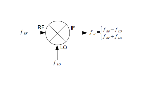
In RF design we call multipliers as frequency mixers. In a superheterodyne receiver, the desired RF signal is multiplied down to an intermediate frequency (IF) using a mixer and a variable frequency oscillator (VFO or Local Oscillator), where there is a multi-stage filter to select the signal to switch to an envelope detector. In other words, one of the two products of the mixer must be equal to the center frequency of the IF filter. To change the frequency at which the radio receives, all you have to do is change the frequency of the VFO.
The figure below shows a block diagram of a desktop AM radio from the late 40’s, where the radio is tuned to stations with frequency frf = frequency of OSC1 – 455 kHz. Changing the frequency of OSC1 changes the frequency at which the radio is set to frf.
Block diagram, schematic image and photos of a typical superheterodyne broadcast receiver.
SSB receivers
Instead of demodulating the radio signal with a shell detector, the SSB receiver converts the IF once more using a second frequency mixer in the audio frequency range (this second mixer is sometimes known as the product detector). The result is amplified and delivered by a speaker.
What is heard on an SSB receiver is actually the radio spectrum multiplied by the audio frequency spectrum so that we can listen to it. You are listening to the actual radio waves.
In this case, the bandwidth of the IF filter is between 1.8 and 2.5 kHz, consistent with the bandwidth of human speech. The center frequency of the IF filter and the 2nd local oscillator determine which sideband is selected, either the upper sideband (USB) or the lower sideband (LSB). USB and LSB refer to the displacement of the human voice above and below the carrier frequency, respectively.
Blog diagram of a 20m SSB receiver and representative graphs of the signals at each stage in the receiver.
SSB transmitters
The SSB transmitter is simply an SSB receiver in the opposite direction. Filters and modern two-balanced frequency mixers work in both directions. The amplifiers are thus connected to relays or PiN dido so that they can be reversed in transmission mode. When you transmit SSB, your voice is converted to the radio spectrum, amplified and transmitted by the antenna.
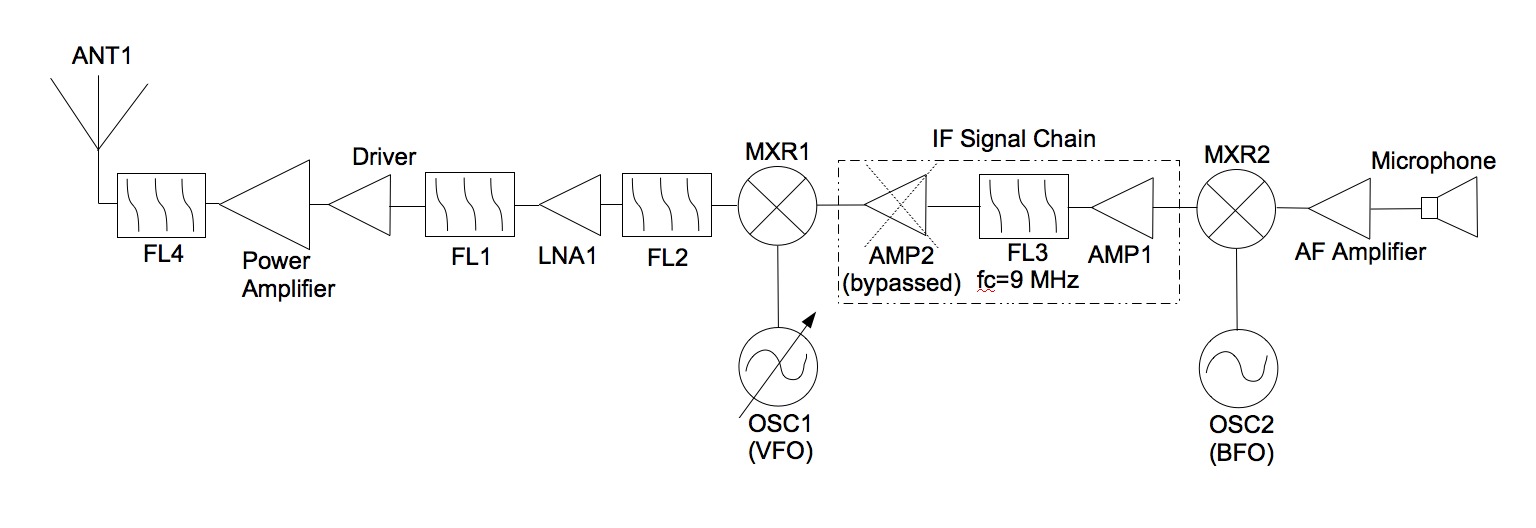
20 m SSB transceiver
The first SSB transceiver I developed was for 20m, which is probably the funniest HF tape. The marine network is at 14,300. Lots of DX during the day. From the coastline in Connecticut, I can routinely work in Western Europe and inland with just 40 watts and a half wave dipole antenna.
20m SSB transceiver built from scratch.
The block diagram of this transceiver is exactly as shown above. You can find many details, diagrams and additional information here. This radio is representative of most SSB transceiver architectures.
next steps
I have abstracted radio circuits to the level of the block diagram. Once the blocks are understood, then the design can be done at a high level. Once the block diagram is in place, then circuits, integrated circuits or modules can be selected to fill the blocks. Some schemes are borrowed from books or scaled from design to book. It is a great source for 50 ohm integrated circuits and modules mini-chains. Others require the synthesis of a custom staircase network, as will be the case with RF filters. These are great resources for finding, borrowing, or synthesizing these schemes or entire radio architectures even:
ARRL Handbook
Solid State design for radio amateurs
The Secrets of Joseph J. Car for RF design scheme
Chris Boweick RF Circuit Design
Rohde communication receivers
QST Magazine
QEX Magazine
Build it:
There is so much more to basic RF design and the only way to really learn is to start doing it. Take as many schemes as possible from others. Blow up your radio together. You will improve in every aspect of the design after every radio you build. Jump straight! There is nothing like the satisfaction of making long-distance contact with a transceiver that you have built yourself. I look forward to communicating with some of you on the air soon!
Recognition
My cousin, Juliet Hurley, MBA, MSF, MAC to edit the type of this publication.
Author Bio
Gregory L. Charvat operates only radio equipment, which builds from scratch, is the author of Short and short range radar systems, co – founder of Hyperfine Research Inc.,, Butterfly Network Inc. (both are 4catalyst (companies), visiting scientist from Camera Culture Group Massachusetts Institute of Technology Media Lab, editor of Gregory L. Charvat series of practical approaches to electrical engineering, and guest commentator on CNN, CBS, Sky News and others. He was a member of the technical staff at MIT’s Lincoln Lab, where his work on wall radar won the best work at the 2010 MSS Tri-Services Symposium, and is MIT’s office at Provost 2011’s research focus. has taught short radar courses at MIT, where his “Creating a Small Radar” course was the highest ranked vocational education course at MIT in 2011 and is widely accepted by other universities, laboratories and private organizations. Beginning in the early days, Greg developed a variety of radar systems, railroad SAR imaging sensors, and phased array radar systems; holds several patents; and has developed many other sensors and radio and audio equipment. He is the author of numerous publications and has received press for his work. Greg received his PhD in Electrical Engineering in 2007, MSEE in 2003 and BSEE in 2002 from Michigan State University and is a Senior Member of the IEEE, where he served on the Steering Committee for 2010, 2013 and 2016. IEEE International Symposium on massive phase systems and technologies and presidencies IEEE AP-S Boston Chapter 2010-2011