If you’ve taken the amateur radio exam in the last few years, you’ve probably come across the topic of software-defined radio (SDR) several times in documents. The affordable RTL-SDR (Software Defined Radio) with Dipole Antenna Kit is an experimental platform that allows the adoption of SDR with practical hardware.
The term SDR stands for Software defined radio you don’t really need any further explanation today. The principle is that parts of the signal processing that were previously performed in hardware (electronic components) are performed digitally in the SDR. In times of increasingly cheap DSPs and powerful microcontrollers, this is a very sensible course of thought.
What do we have here?
The history of this radio module system, known from the RTL-SDR blog, began, as often, with coincidence. Rumor has it that the Linux kernel developer has discovered that the RTL2832 integrated circuit manufactured by RealTek is more than just a classic DVB-T decoder. It can collect I / Q samples and send them directly to the host, a feature designed by the chip maker to decode FM radio. The SDR kit described here is for admission. It is not possible to send with the module. So this is radio in the sense of the word use.

According to the documentation and information in the datasheet, the chip can monitor spectrum up to 3.2 MHz in “real-time operation”. Practical experience shows that when this band is fully used, the samples are lost. Therefore, the realistic bandwidth is limited to a maximum of 2.8 MHz or slightly less. In the documentation, Elektor even advises not to process more than 2.4 MHz at a time.
The IC RTL2832 itself does not have a built-in tuner to take care of limiting the recorded frequency range. Therefore, something similar is found in USB sticks based on RTL2832. The USB module supplied by Elektor is a tuner manufactured by Rafael Micro with the designation R820T, the interior of which is shown schematically in the following diagram.
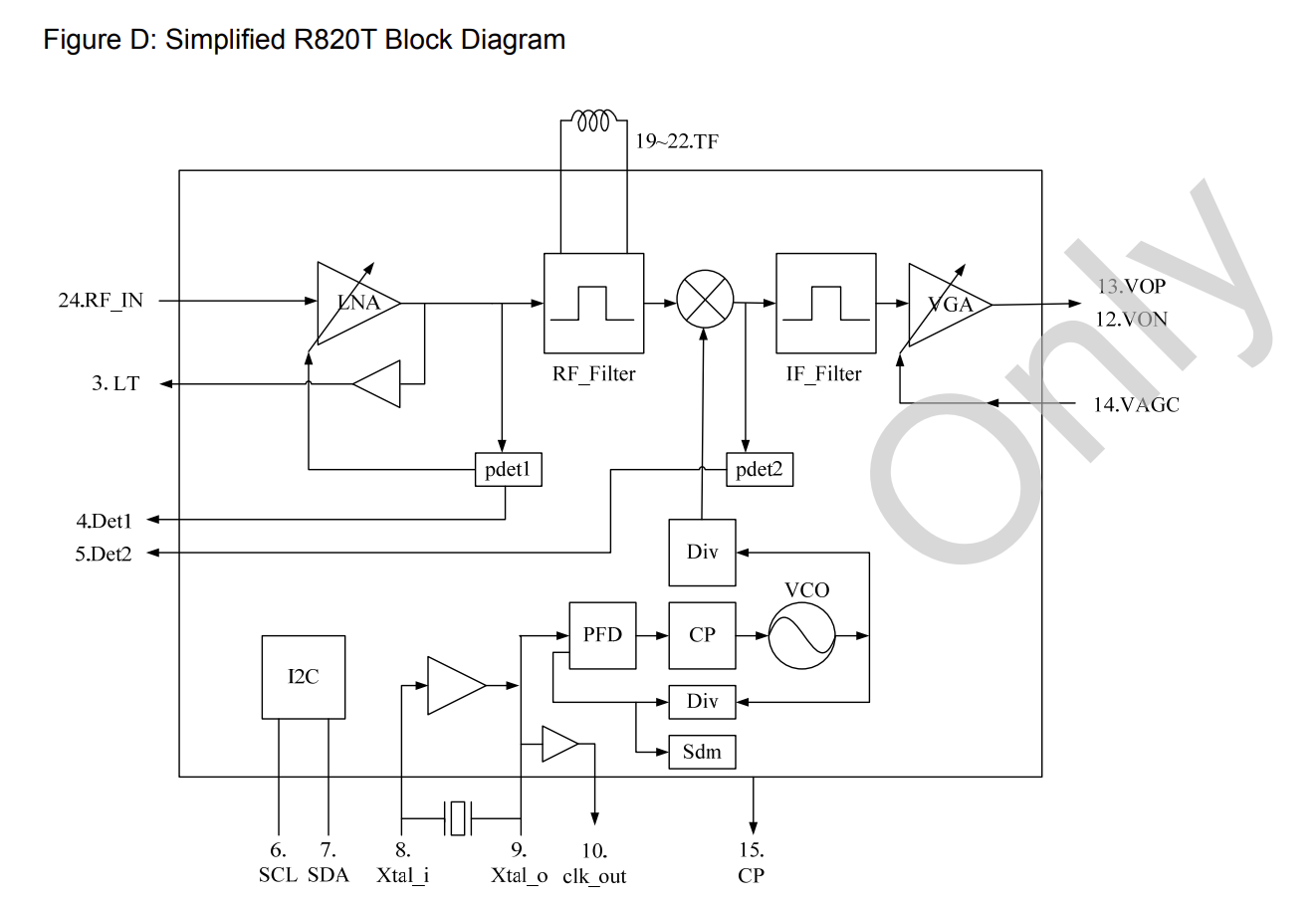
Unfortunately, the manufacturer based on Formosa does not provide enough information about the behavior of its chip. The above presentation is taken from unofficial data sheet.
Getting started with SDR
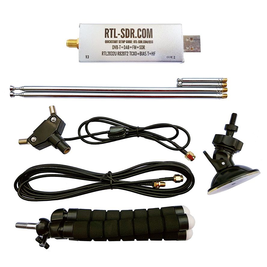
Such SDR USB sticks are available in several variants. The “luxury version” was in the Elektor package. In addition to a tripod and suction cup holder for the antennas, only a dipole T-shaped part is included (unfortunately), but two pairs of extendable antennas of different lengths can be used. The shorter antennas are 5 to 13 cm long and cover the frequency range from UHF to about 1.5 GHz. The longer samples are 23 to 100 cm long and cover the frequency range from VHF to UHF. Note that these antennas are for reception only. Transmitter adjustments will also be required at this time.
I performed the following steps without the extension cord included. For my experiments, I wound the two longer antennas (as shown below) on the dipole adapter and connected its connecting cable directly to the USB dongle.
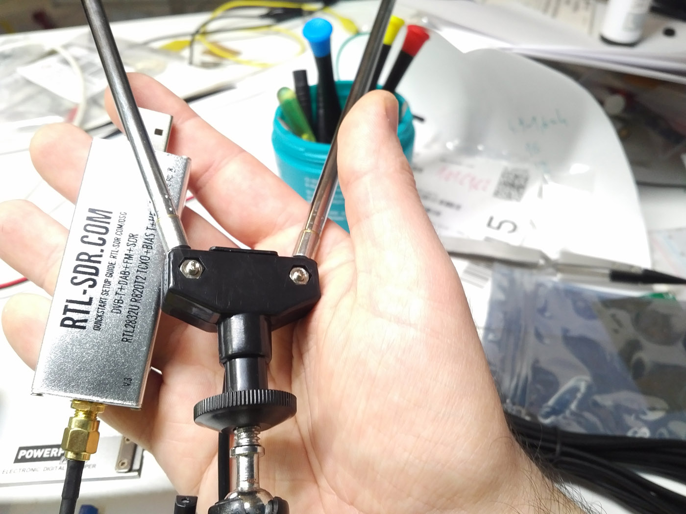
The cheaply produced dipole adapter for the antennas works smoothly in practice. A perfectly fitted Phillips screwdriver should definitely be used to tighten the screws if you do not want to damage the screw heads.
Before connecting the USB stick to a computer, you need to install the necessary software. For the operation of SDR as a standard, a computer with Windows 10 appeared. However, Linux also works! This is a great thing for me because I usually work on a Linux computer. More information on this topic can be found at Quick Start Guide.
For software go to AirSpy because it offers software for various SDR keys. The Download software package for Windows SDR is suitable. The downloaded archive is then completely unpacked into a local working directory. This is necessary because the installation process will not start if you run the .exe file directly from the archive. For legal reasons, AirSpy cannot include drivers. Instead, they are downloaded directly from the provider’s server using the install-rtlsdr.bat batch file. Note that the zadig.exe file is about 5 MB in size. This isn’t really much these days, but downloading from a provider’s server occasionally proves unreliable.
After installing the software and drivers, the dongle is connected to the computer via USB. Here, the discovery of a plug-and-play device included with Windows must begin. The next step is performed only when Windows displays the message “The device is ready for use.” The driver downloaded through the package is not yet functional at first, so the zadig.exe file should be started in the next step by right-clicking with administrator rights.
Zadiq is a tool that specializes in replacing USB device drivers that Windows offers as standard. The first task is to find the USB key. It is usually called “Bulk-In, Interface (Interface 0)”. However, this task is complicated by the fact that the tool filters the displayed USB devices. To find the device, you must activate Option> List of all devices and deactivate Option> Ignore Hubs or Composite Parents. Then click on the big button to replace the driver. Possible security warnings should simply be ignored.
One, two, AirSpy is over
The AirSpy software is written in C #. Double-click the SDRSharp.exe file to start it. Just ignore any error message. In the next step, you need to select the USB dongle in the Source field. The correct type is RTL-SDR USB.
As a precaution, you should turn down the volume so that you are not startled by loud noise. Theoretically, you can click the play symbol now to update the real-time display and chase the spectral components to the audio output. Usually, however, the gain is set very low, so you have to click on the small gear symbol. The software responds by displaying the pop-up window shown below, in which you can increase your profits using the slider.
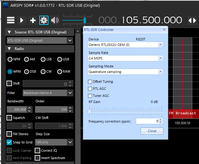
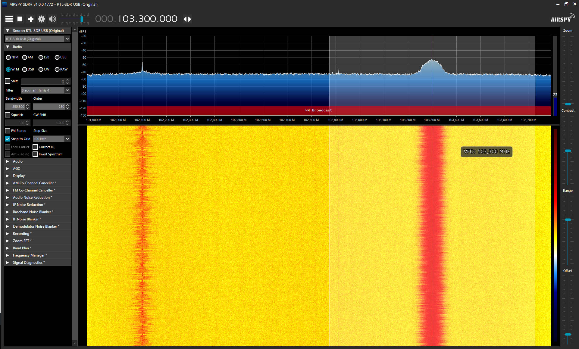
You can now start searching for a certain radio frequency. The following figure shows what I was able to capture near my lab.
SDR extension
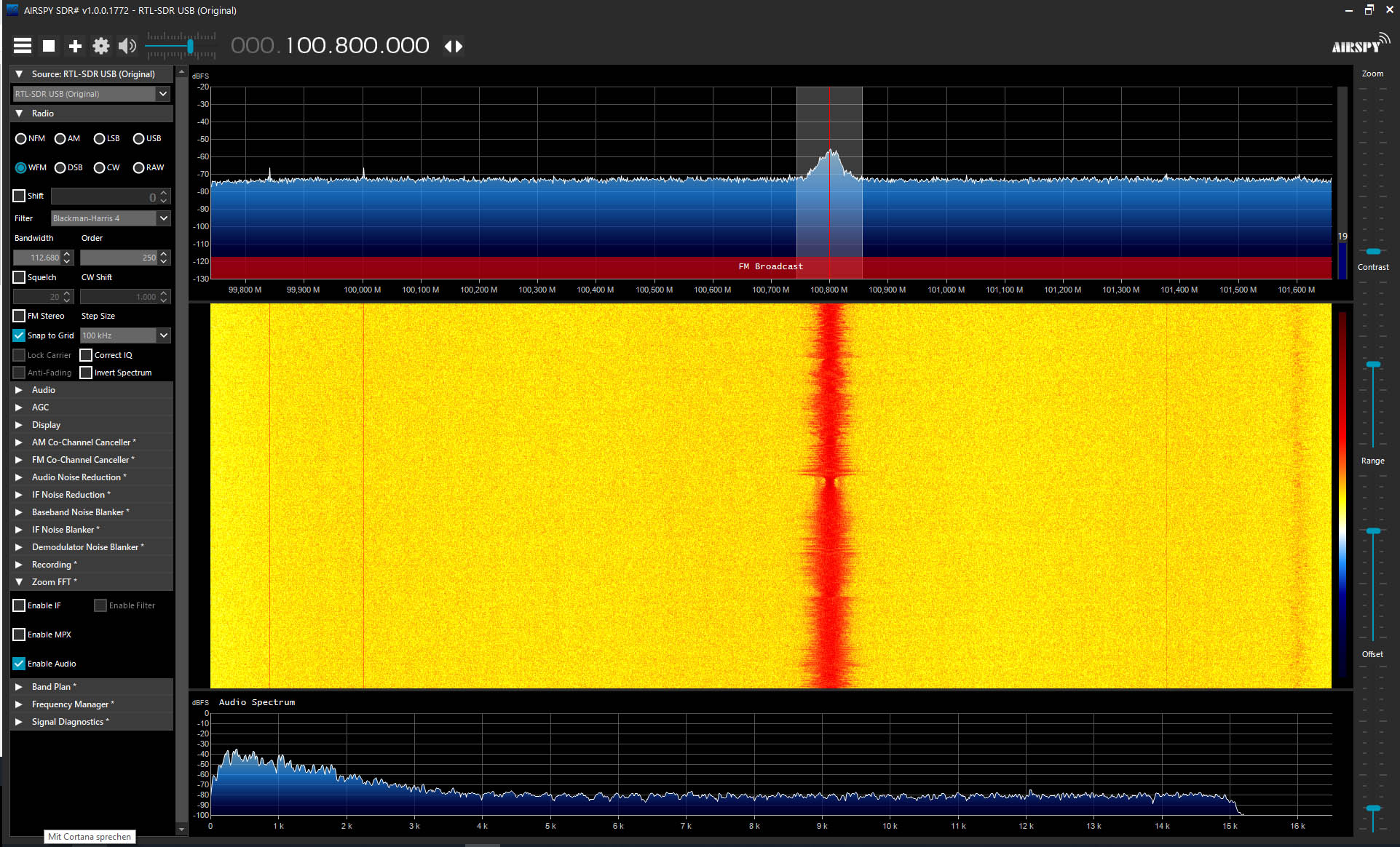
When I was shown a spectrum analyzer from an American manufacturer a few years ago, I realized that it was more of a computer than a classic spectrum analyzer. Much of the device’s intelligence was provided by software plug-ins that interpreted the data provided by the measurement system. It’s quite similar with this SDR system: The toolbox shown on the left side of the screen contains several dozen plug-ins whose settings can be expanded by clicking on them. For example, I experimented with FFT audio. The result can be seen in the next photo.
The capabilities of “signal processing” did not go unnoticed by the user community. There is extensive additional software which even decodes aircraft transponders in addition to various amateur radio protocols.
If you want to program with Visual Studio, this introduction will help you. However, basic knowledge of C # and Visual Studio 2017 is required.
The RTL-SDR kit as a cheap alternative
If you’ve always looked for some kind of real-time spectrum analyzer, you’ll find the “RTL-SDR (Software Defined Radio) with Dipole Antenna Kit” a cheap alternative. The tool is suitable for amateur radio amateurs as a type of automated receiver with rich visualization capabilities. What they do with it is left to their imagination. If you use your kit in a particularly innovative application, the editors of Elektor will surely enjoy your feedback!