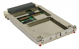

The military is based on open standards and SDR – the CommAtility board with conduction cooling
In the embedded industry, he has over 30 years of experience in using building blocks based on open standards in defense applications. Vendors believe that it takes a lot of trust from the defense equipment manufacturer to choose COTS (commercial ready-made) components. Durability of deliveries, high quality production and testing, as well as the ability to maintain equipment in the field are critical attributes that suppliers must demonstrate.
Once trust is established, the benefits of modular building blocks based on open standards can be realized. For military deployment, although there must still be system-level qualifications, each unit that can be purchased from finished production saves implementation time, reducing development costs and risk.
Ready with open standards
The ability to intercept, monitor and decode communications must keep pace with evolving threats. Although COTS technologies are not always available, they provide valuable choices with shorter design cycles.
The armed forces need the most capable software-defined radio / electronic warfare (SDR / EW) equipment. COTS units facilitate the updating of standard-based equipment, provided that the standards in question are widely maintained. There is a proliferation of open standards as more industries and markets realize the benefits. In general, they can be divided into three categories:
- those applicable to low-cost, single-processor systems
- multiprocessor architectures managed by a small group of manufacturers
- multiprocessor architectures managed by a wide group of vendors and end users.
EW / SDR equipment needs many connected processing elements, so it naturally falls into the latter category. Several open standards can be considered appropriate, including CompactPCI Serial and Rugged MicroTCA from the PICMG standards body, plus VITA’s VME and VPX standards.
Built-in benefits
CompactPCI boards and AdvancedMC modules (used in MicroTCA systems) still do not have enough momentum in the defense community and are therefore not considered the best choice, although they have some technical advantages.
Many VME boards have been deployed in military and space activities and this may still be a valid option for updating an existing system. However, the obvious choice for a new design is the VPX standards portfolio.
VPX was originally introduced as VITA 46 and then supplemented by the OpenVPX VITA 65 initiative. VITA 46 offers great flexibility in the choice of pins, denying some of the benefits of COTS hardware, allowing vendors to create unique solutions.
VITA 65 is guided by the need for customers to standardize certain interoperability profiles and stimulates a wave of VPX deployments, where de facto choice is now available, allowing “best-in-class” modules to be selected from alternative vendors.
Mapping the backplane in a VPX solution is important. Although driven by a set of predefined slot profiles in the specification, there is a choice of backplane architectures to implement. The VITA 65 specification defines profiles precisely.
Electronic warfare
The EW-enabled configuration includes a single Intel control processor combined with multiple DSP / FPGA cards via PCIe and an Ethernet switch. An example of command and control is the TR B1x / msd board from Concurrent Technologies, which is based on a fourth generation Intel Core processor.
The board has two x4 PCIe data plane “fat pipe” connections, compatible with the VITA 65 MOD3-PAY-2F2U-16.2.3-3 profile. The “2F2U” profile refers to the presence of two grease tubes (four strips) for use in the data plane plus a pair of ultra-thin (one strip) tubes for control use. The final figures identify both fat tubes as PCIe Gen 2 compatible and the two ultra-thin tubes as 1000Base-BX control plane interfaces.
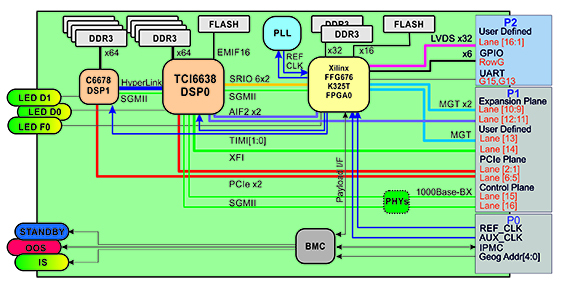
Figure 1: VPX-D16A4-PCIE block diagram showing rear input / output
Four CommAgility VPX-D16A4-PCIE DSP / FPGA boards (Figure 1) are used for signal processing and also have PCIe connectivity. The two DSPs on each board have their own x2 PCIe connections to the rear board, so the TR B1x / msd control board is configured with an x4 data plane split into two x2 tubes. This allows data to be sent between the individual DSPs and the control and management board.
Smaller, cheaper VPX configurations can be created without the switch module using a backplane that has specific connectivity, such as an Intel-based control processor that has an x4 PCIe connection to two DSP / FPGA boards in the slots. on both sides of the processor.
Robust kit
Many EW / SDR deployments must operate in a conductively cooled rather than air-cooled environment, withstand high levels of shock and vibration, and have a coating to protect against factors such as moisture and contamination.
The VPX-REDI specifications (VITA 48.0) guarantee the strength of COTS-based military systems and focus on aspects that allow favorable size, weight and power (SWaP).
Nigel Forrester is a technical marketing manager at Simultaneous technologies and Paul Mocks is CTO CommAgility